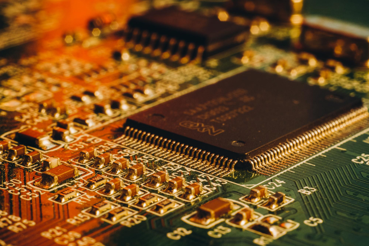
A crucial factor determining the quality of mounting electronic components on a printed circuit board (PCB) is a reflow procedure used primarily for solidifying a solder material, which depends on a particular type of PCB assembly. The more experienced an electronics manufacturing service (EMS) provider is, the more optimized profile will be built.
Standard SMT reflow oven profile
It is typical for EMS providers to have at least one standard set of settings for their oven profile that they used in the past. Yet, working with different projects allows EMS providers to create more customized profiles dedicated to different types of PCBAs.
While there is a range of PCB assemblies without any specific requirements, there are also units with sensitive elements that have to be treated at lower temperatures. Others require higher temperatures due to a large number of electronic components located close to each other.
Assel is an experienced Surface Mount Technology provider, to find out more about SMT check: Asselems.com
Reflow of sample PCBA
The impact of a chosen reflow oven profile on a PCBA is checked with a sample unit.
Thermocouples are attached to several regions of a PCBA, which should be added to the components of an assembly with different levels of heat dissipation. An ideal number of thermocouples is between three and six depending on a PCBA size.
It is essential to attach thermocouples properly since inappropriate settings can disrupt measurements. For instance, using tape can move thermocouples and result in measuring the air instead of the elements of PCBA.
Thermocouples are then attached to a data logger for monitoring changes.
SMT reflow oven profile analysis
The recorded information is used for analysis and further adjustment of the oven profile. The goal is to optimize the process so that the measurements fall within the tolerance range specified by a solder paste manufacturer for certain properties of the reflow process. There are three particularly important areas for building an ideal SMT reflow profile.
First of all, the so-called ramp should be between 1 and 3°C. This term can be understood as the speed of temperature changes, which is particularly noticeable at the beginning of the reflow process. The ratio going beyond this limit can cause component damage.
Secondly, the soak zone which helps to maintain the same temperature in various components of a PCBA should occupy between 33 and 50% of the heat tunnel.
Finally, it is critical to measure the time of exposure of a PCBA to the temperature reaching beyond the reflow temperatures. The range of reflow temperatures varies between 230 and 250°C.
Conclusions
The plan for building an SMT reflow oven profile includes choosing an initial profile and examining a reaction of a sample PCBA to the existing conditions of the reflow process. If needed, the settings are readjusted to meet the tolerance requirements set by a solder paste manufacturer for a ramp, a soak zone, and the time of exposure to the temperatures above the reflow area.
